5" gauge SMJ 16
|
5" gauge SMJ 16 |
|
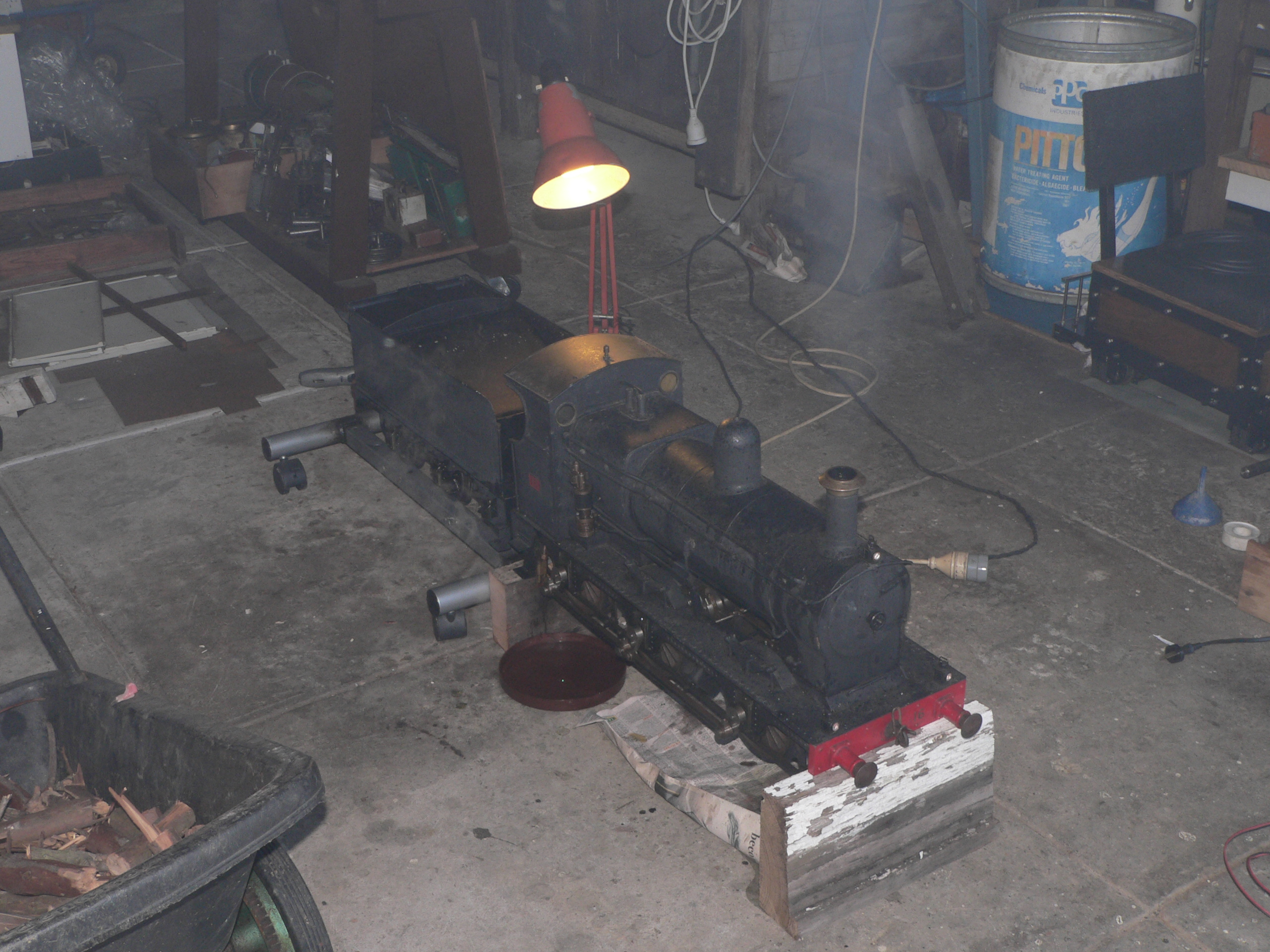
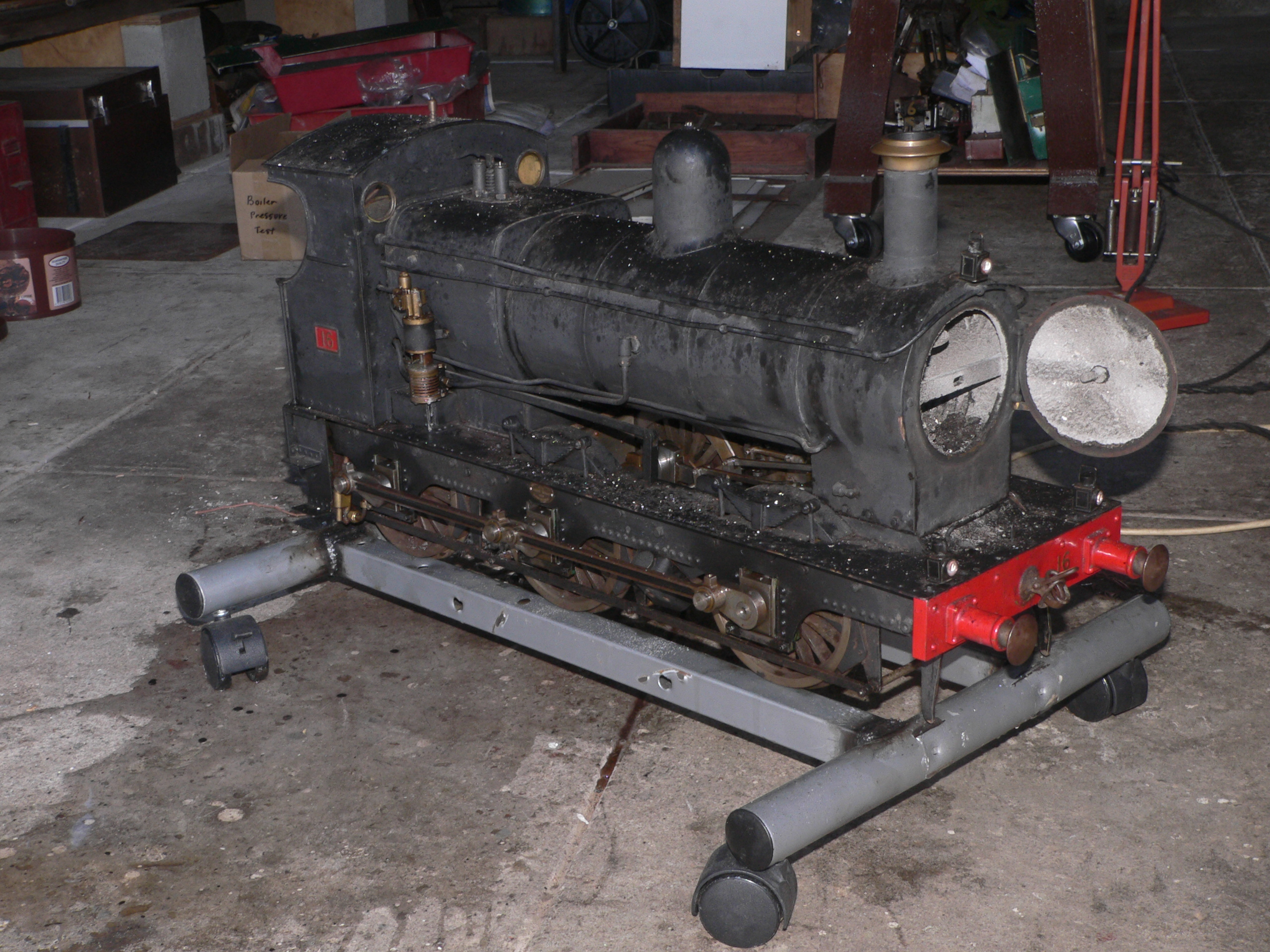
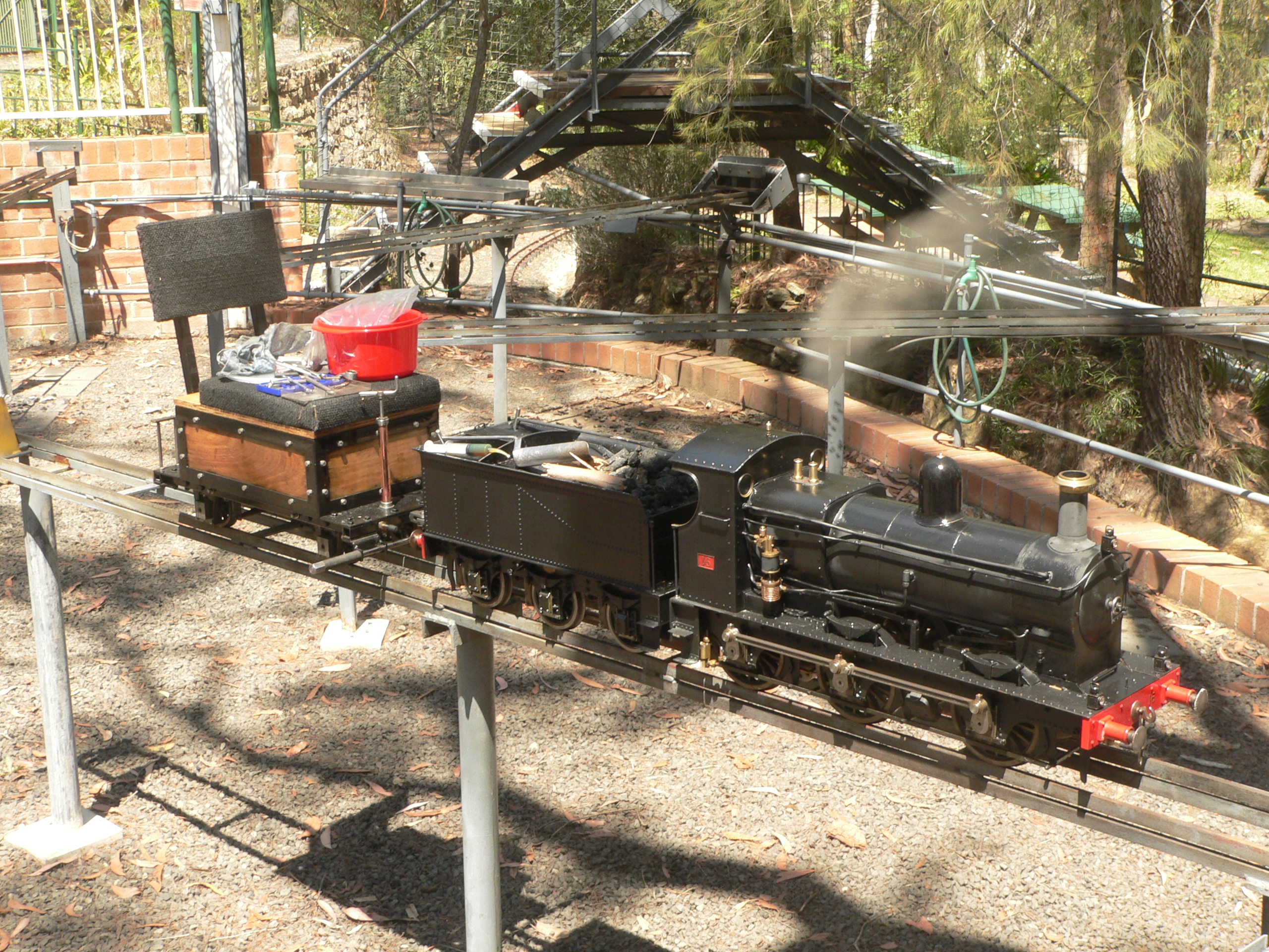
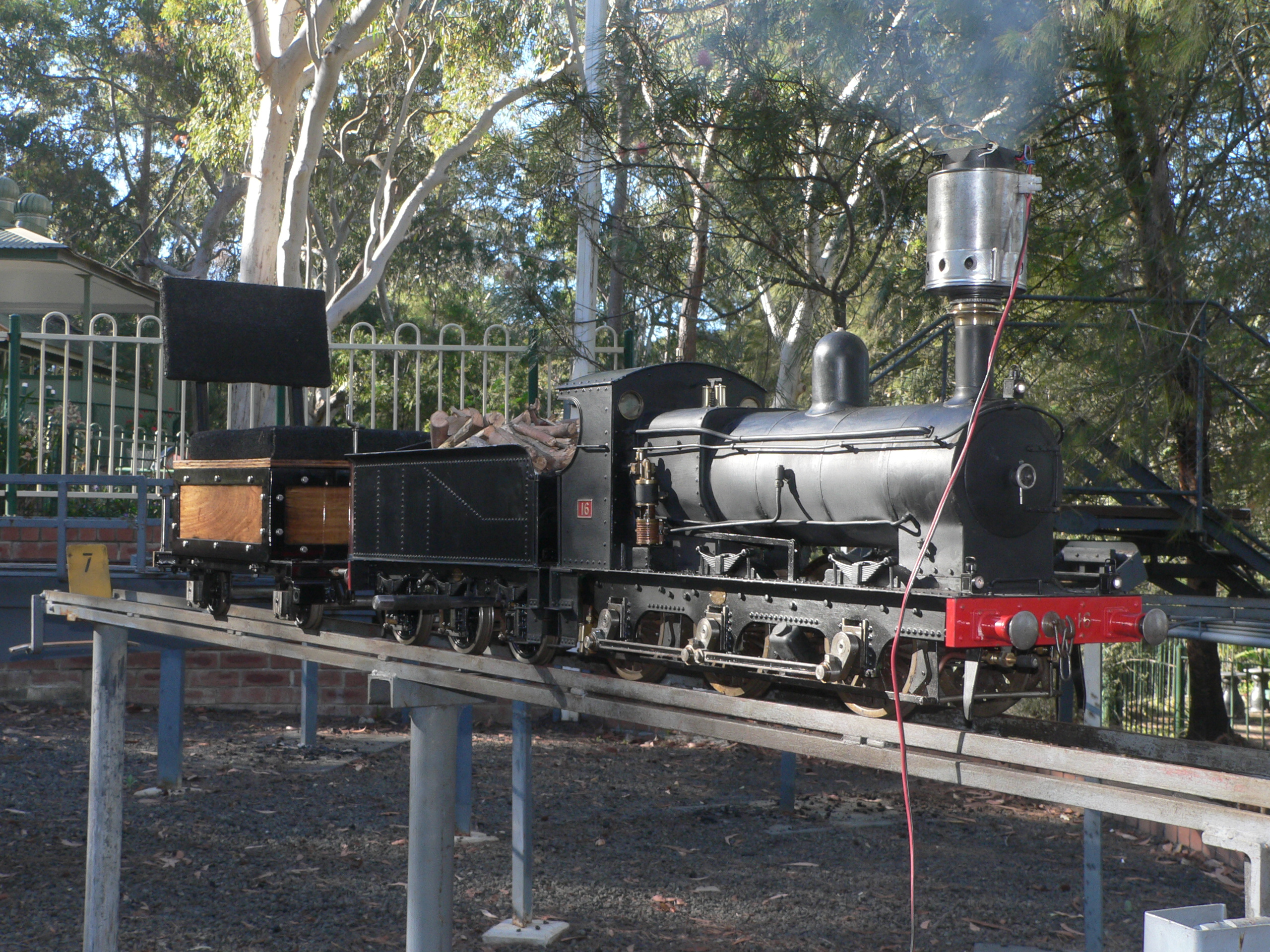
This 5" gauge loco was built by Jack Esdaile many years ago and apart from a recent test steaming hasn't run in over 30 years. The major issue is that the boiler is unregistered. I've now got this loco to fix any problems and hopefully get a boiler certificate so it can run on club tracks. This report details the work and progress on the loco's return to service. The first photo shows myself and Graeme (the owner) after we'd done the first hydro test.

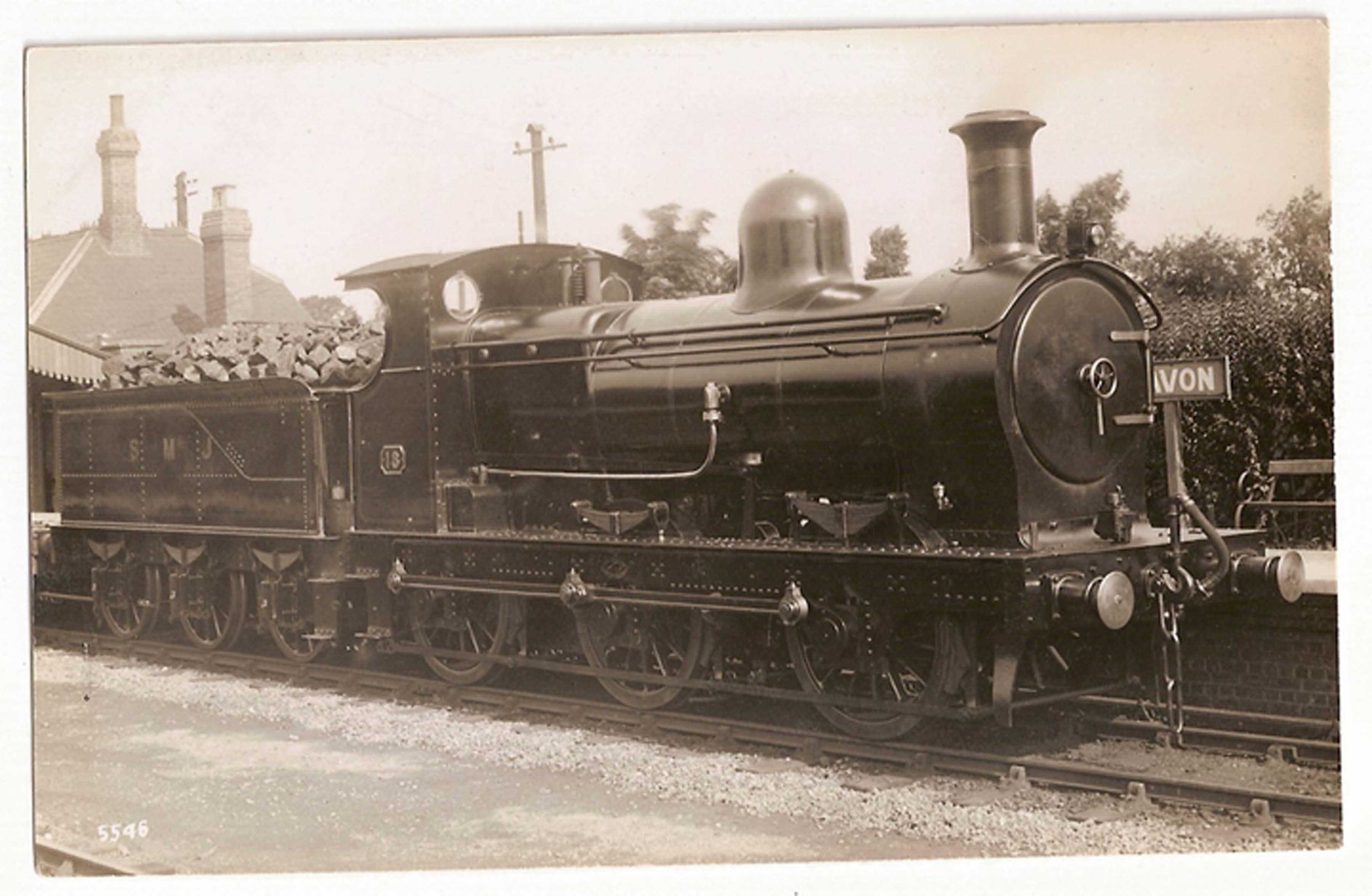
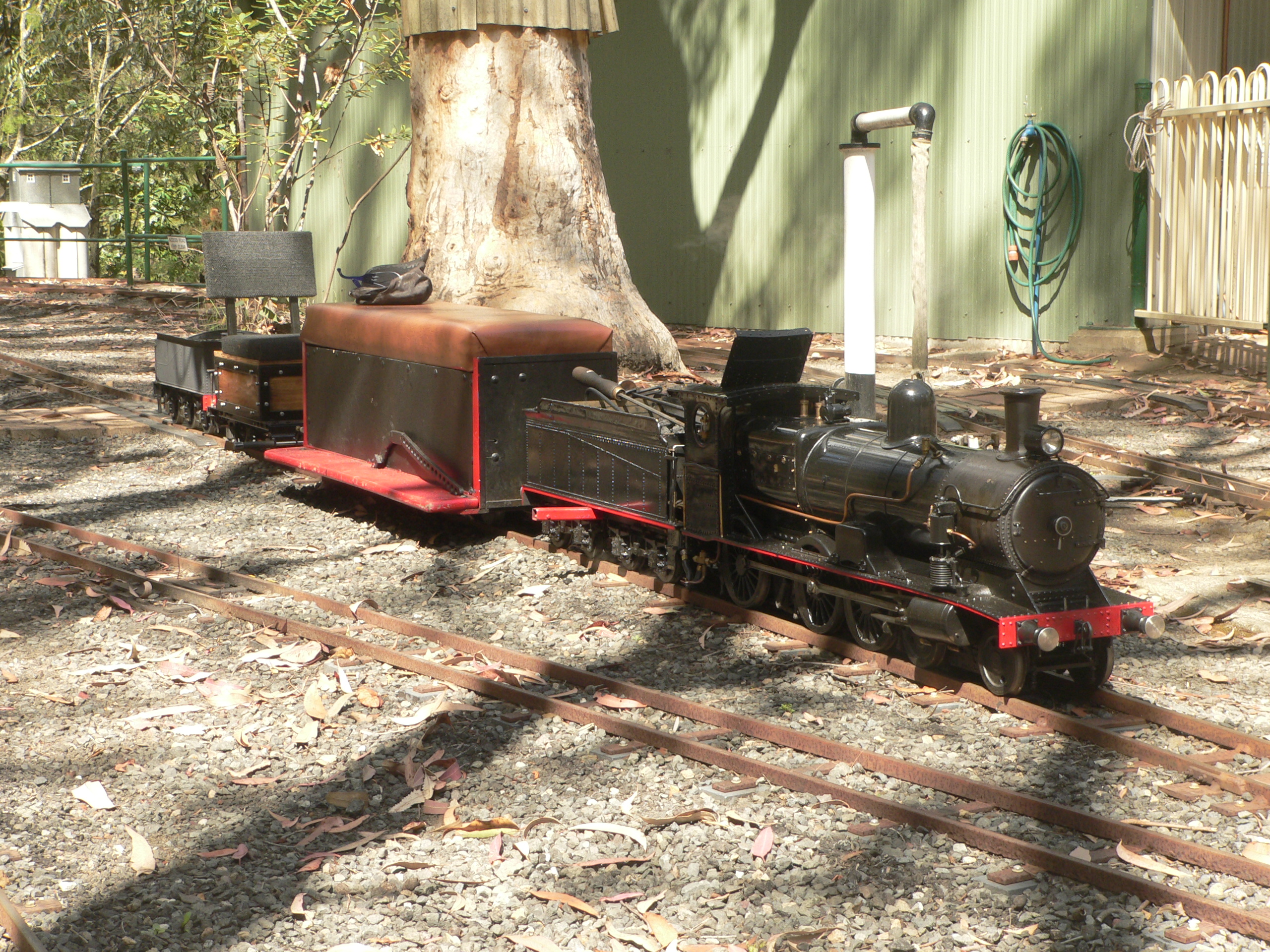
The loco is based on one that ran on the Stratford-upon-Avon & Midland Junction Railway. It is an 0-6-0 tender engine with outside frames. It has inside pistons with slide valves on top and slip-eccentric valve gear. Boiler feedwater is supplied by an axle pump, a donkey pump, an injector, and the emergency hand-pump in the tender. The safety valves lift at 75psi. The engine with tender is 1260mm long.
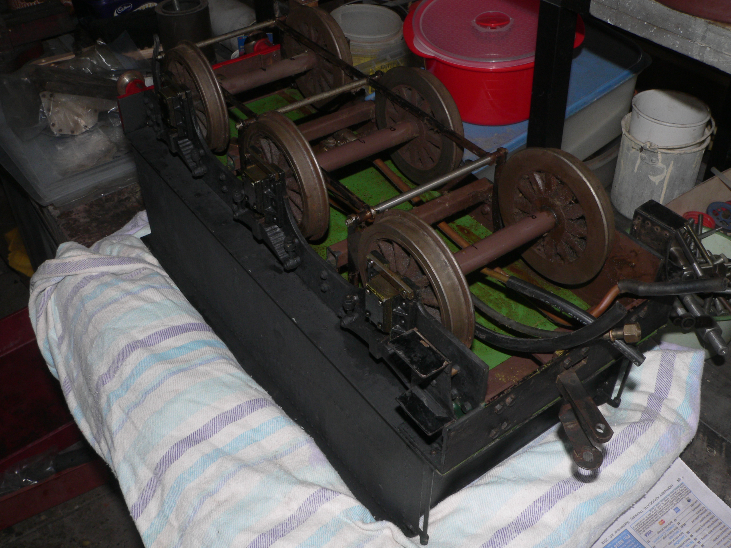

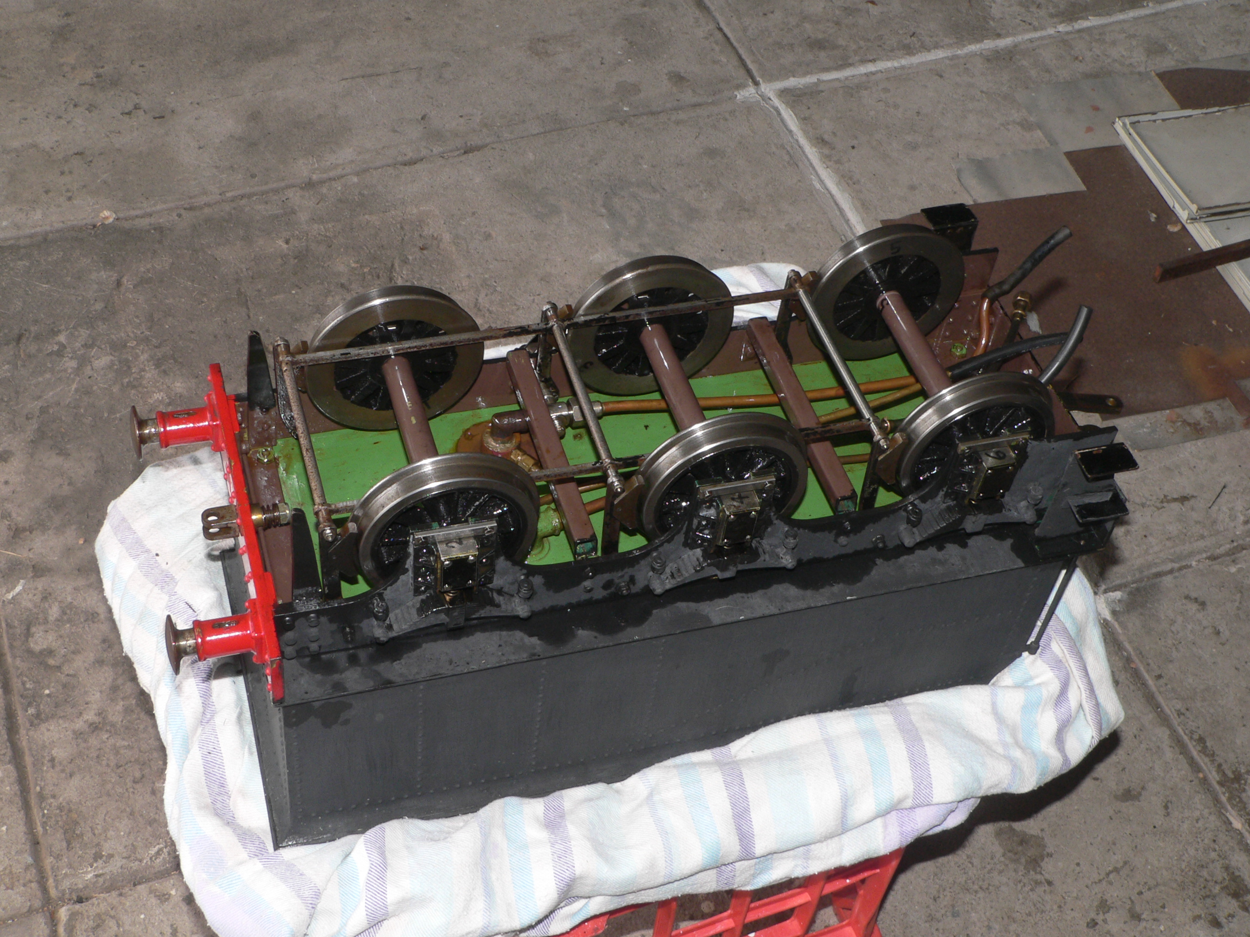
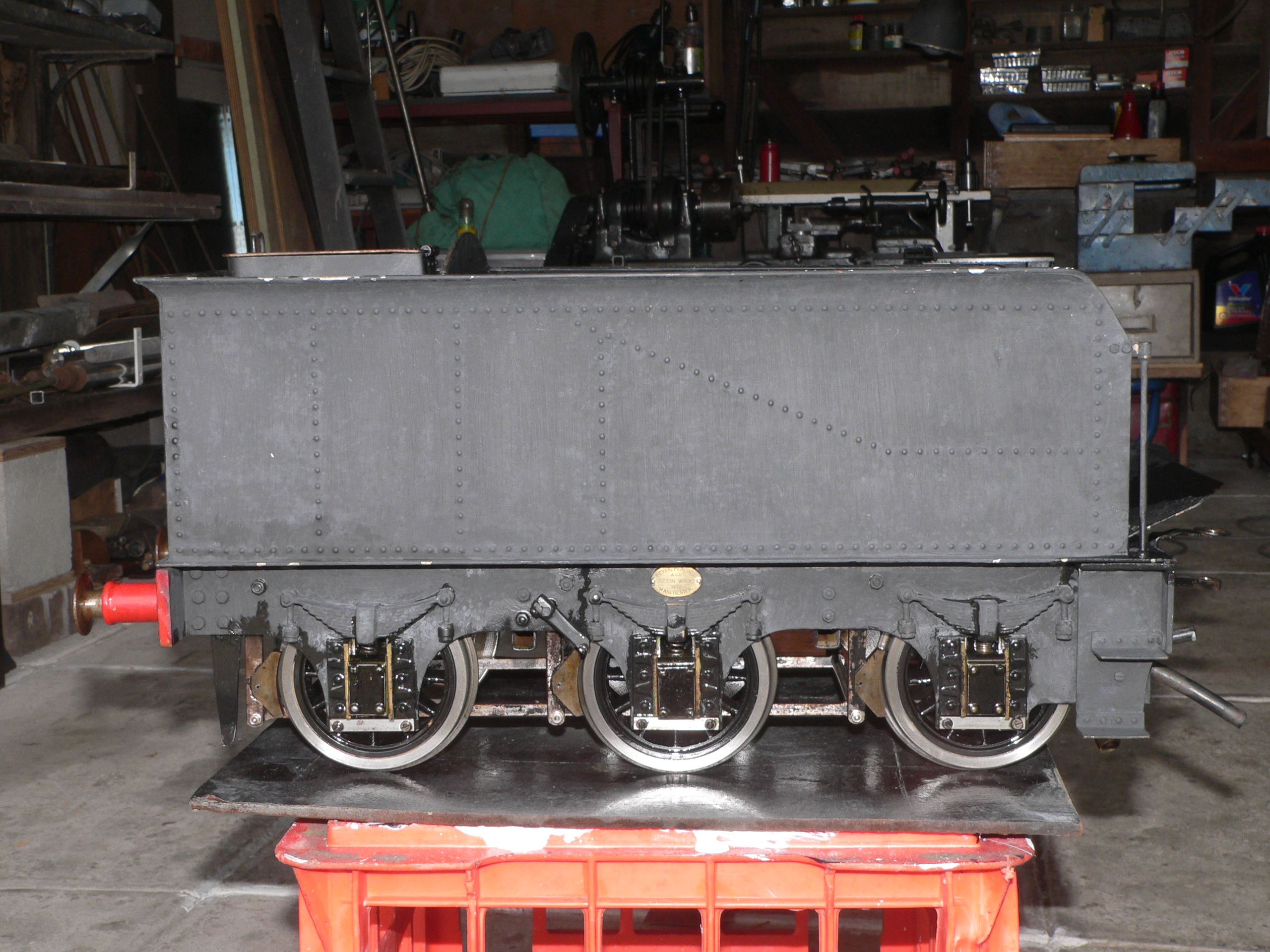
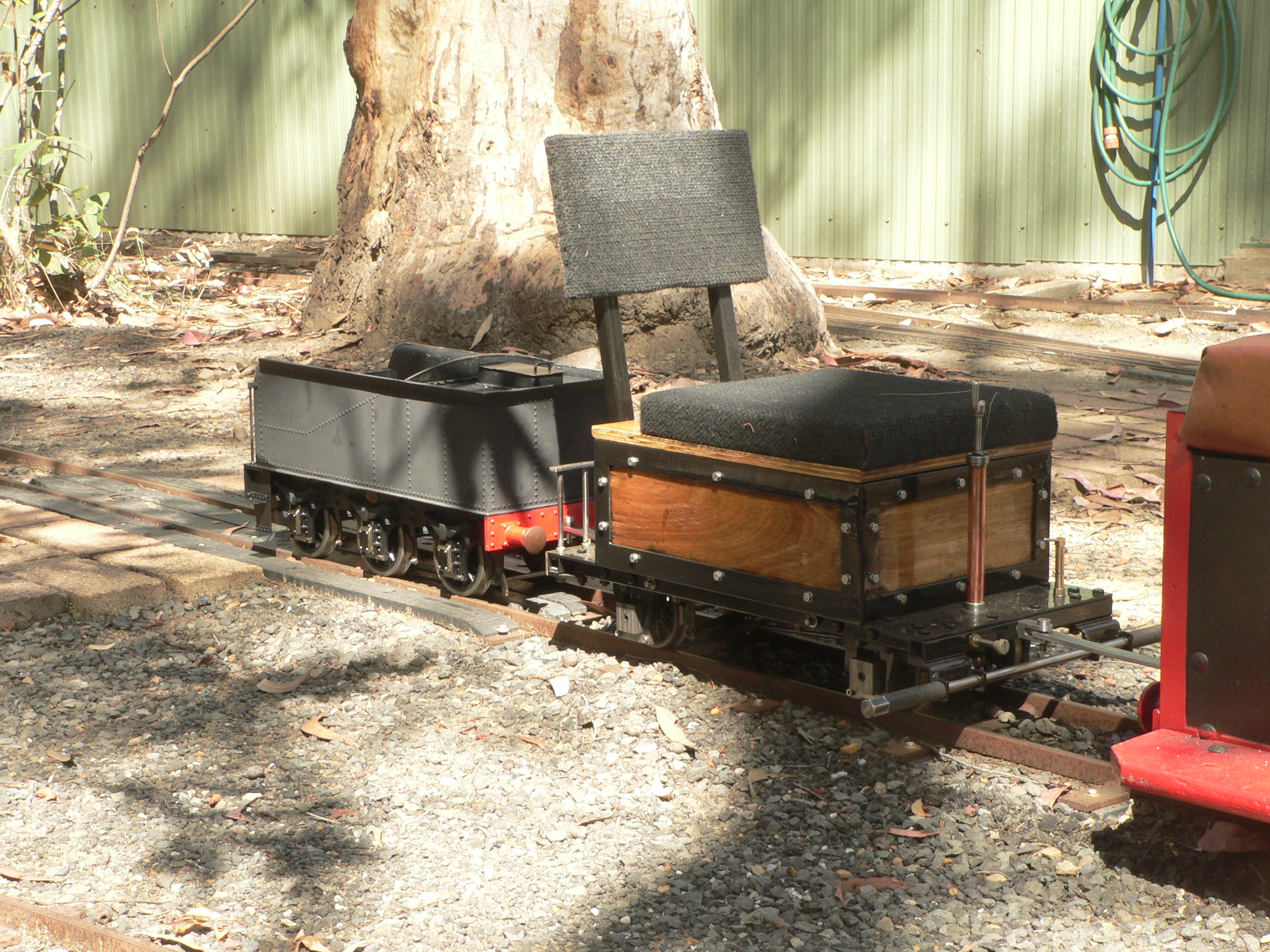
The six-wheeled tender has no provision for footpegs and the light springs confirm that it's not meant to take any weight from the driver. The front axle was tight due to no side play and after disassembly I found the wheels were loose on the axle. A bit of cleaning and Loctite 262 soon fixed this. Axle no. 1 is slightly longer than axle no. 2 and swapping these axles fixes the tightness problem because the horns for the second axle are slightly farther apart.
The flange profile is the AALS preferred profile (116mm back to back) rather than fine scale. I didn't know the narrow-gauge profile was defined so long ago. Subsequently I found that Sydney Live Steam Locomotive Society documented this profile back in 1966 and still recommends it. It's very close to the AALS preferred profile and I think it's better because it's more technically correct.
The tender has outlets for its hand pump, the axle pump and donkey pump, and for the injector. There is a return for the axle pump.
The rear coupling is a clevis that is suitable for an AALS Type B pin and bar. There is no provision for vacuum brakes (at the moment).
Fixing the tight axle was more involved than expected. I'd numbered the axleboxes and wheels left-to-right and front-to-back. Eventually I found the best order was the total opposite. As the screws for the horn stays were loose I suspect that someone removed the wheelsets years ago and put them back in the wrong order.
The final step here was to ensure the tender ran properly on our local track. We towed it at the back of a small train and checked it ran smoothly over the points. Good trackwork should be suitable for both fine scale and narrow gauge flanges. Due to differences in these profiles the trackwork must be very precise to accommodate both. The test went well and the tender probably travelled 20 miles that day.
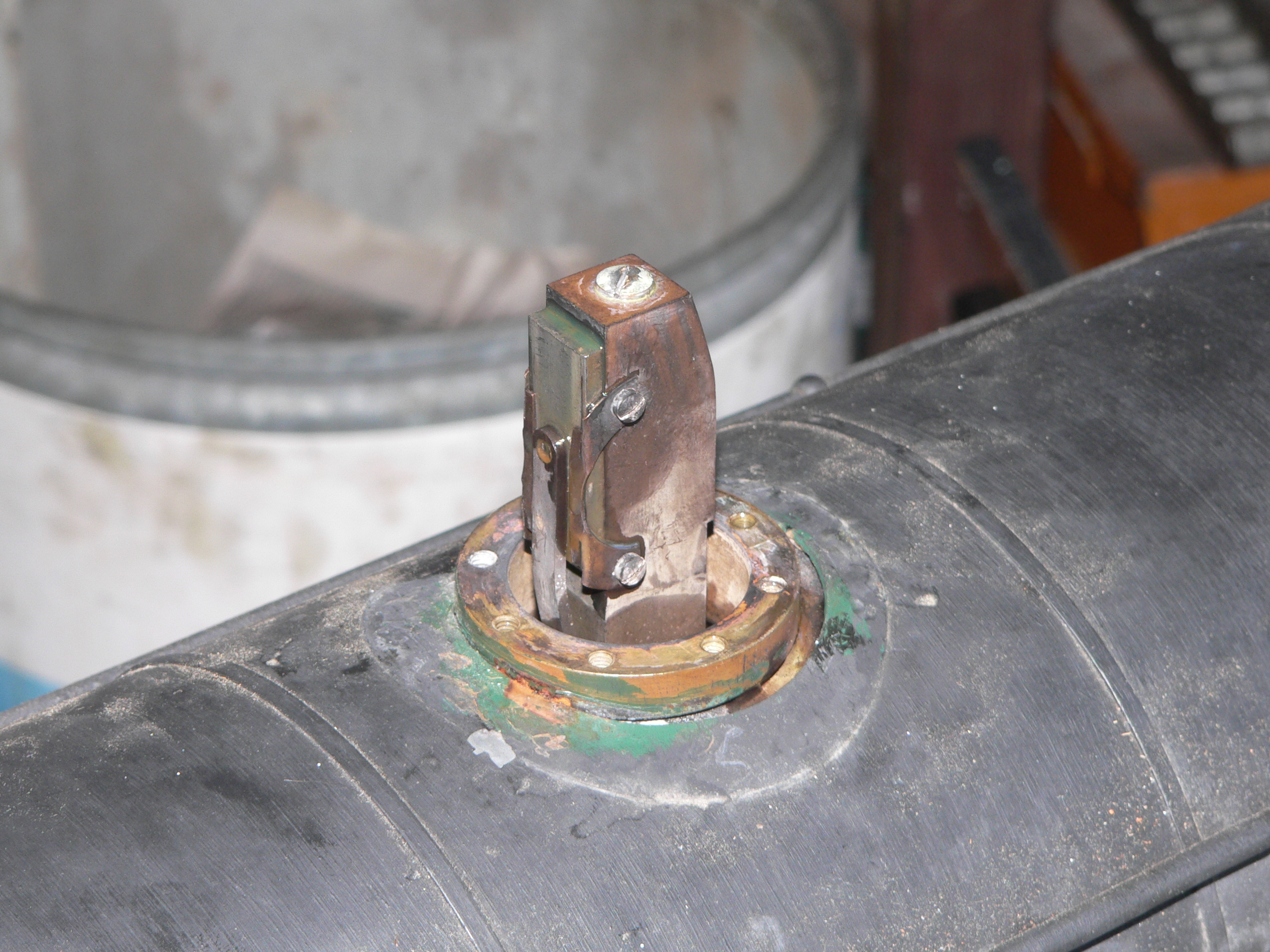
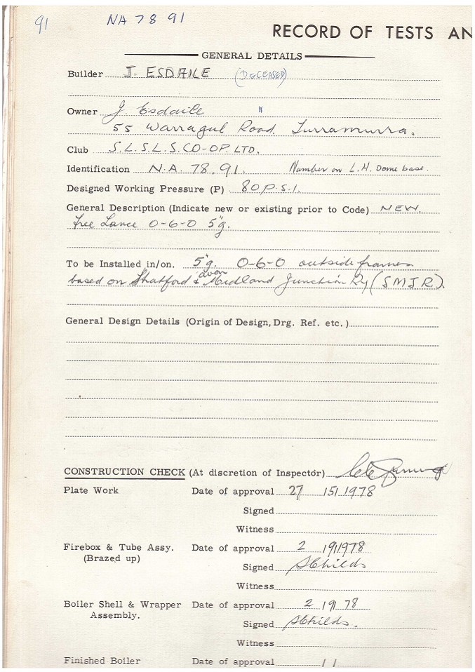
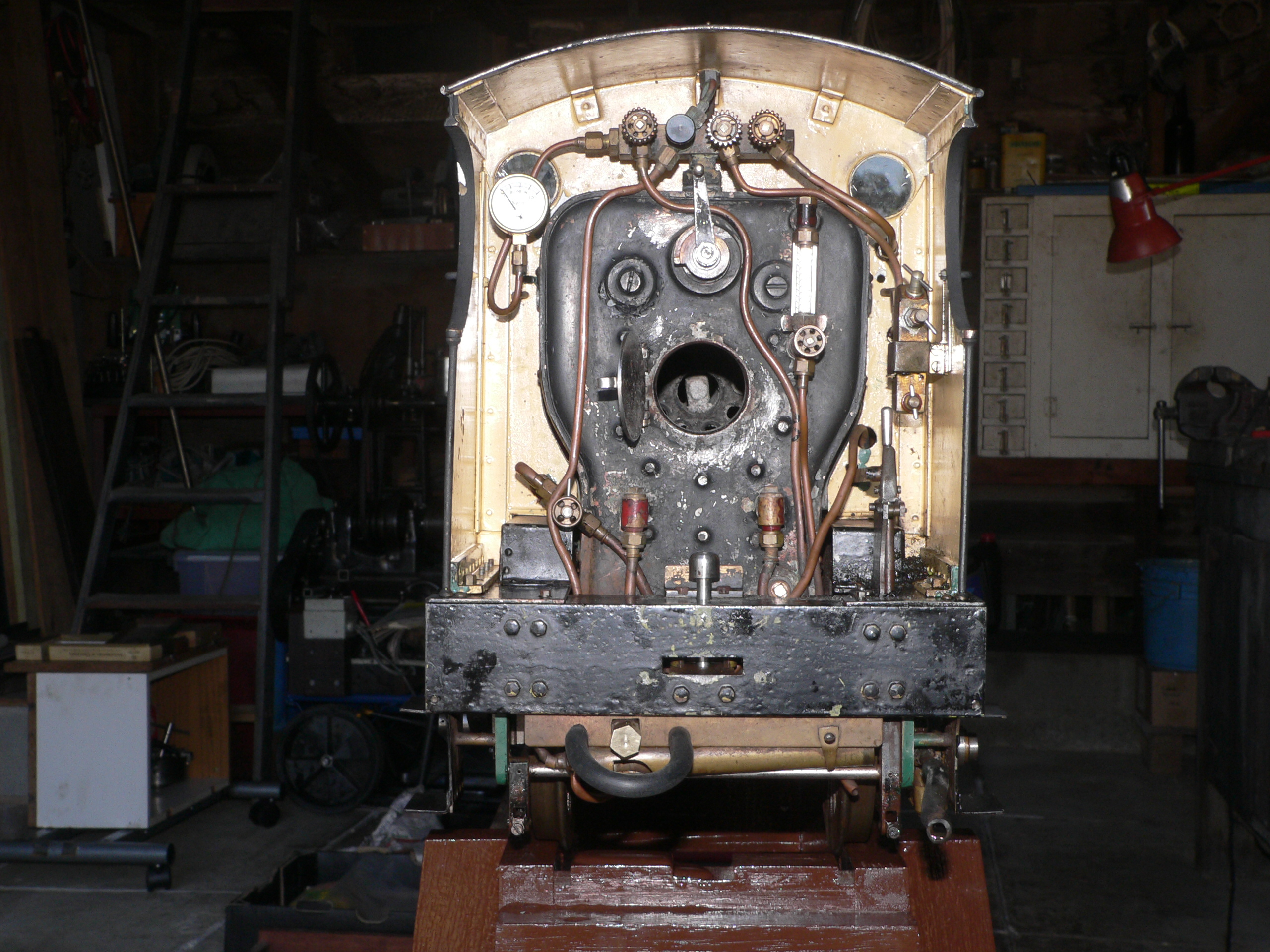
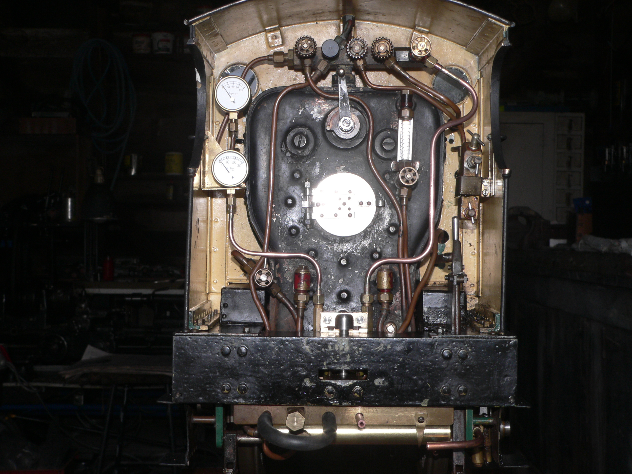
In preparation for visiting a boiler inspector to find out what had to be done to register the boiler I wanted to do another hydro test and steam test. When I started the hydro the regulator was leaking like a sieve. I removed the dome cover and lo and behold there was a boiler registration code (NA.78.91) stamped on the flange for the dome. What great news; the leaking regulator was a blessing in disguise because it is much easier to renew registration of a boiler than register an old one that has never been inspected (including during construction) and approved.
The regulator plate is held by two spring plates that push it against the housing. The spring pressure was really weak so I bent the plates slightly and this fixed the leak problem. Normally the steam pressure would hold the plate against the housing and the leak when first raising steam would not be noticeable.
The safety valves lifted with 75psi showing on the pressure gauge in the cab so I did the hydro at 160psi according to my large and hopefully accurate gauge. My gauge shows that the cab gauge reads a bit low so I'd say the 75psi reading is 80psi in reality. The only leaks were drips from two check valves so everything is looking good here. I'm using boiler treatment in the water to reduce any scale in the boiler. There is a blowdown valve at the back of the foundation ring which is not quite the right place but there is no room for any valve at the front of the foundation ring.
The next day I did a steam test with the loco on blocks so I could test the motion including the axle pump. One safety valve started leaking and I later found the problem was a bit of PTFE tape on the seat. I'd used this tape when fitting the valves. It works well but like Silastic it can get everywhere and cause hassles. I didn't have any coal or char so the entire test was done using sticks from some friendly local trees.
The steam test went for two hours and didn't use as much wood as I had expected. The ash and oil everywhere reminded me why these tests should be done outside.
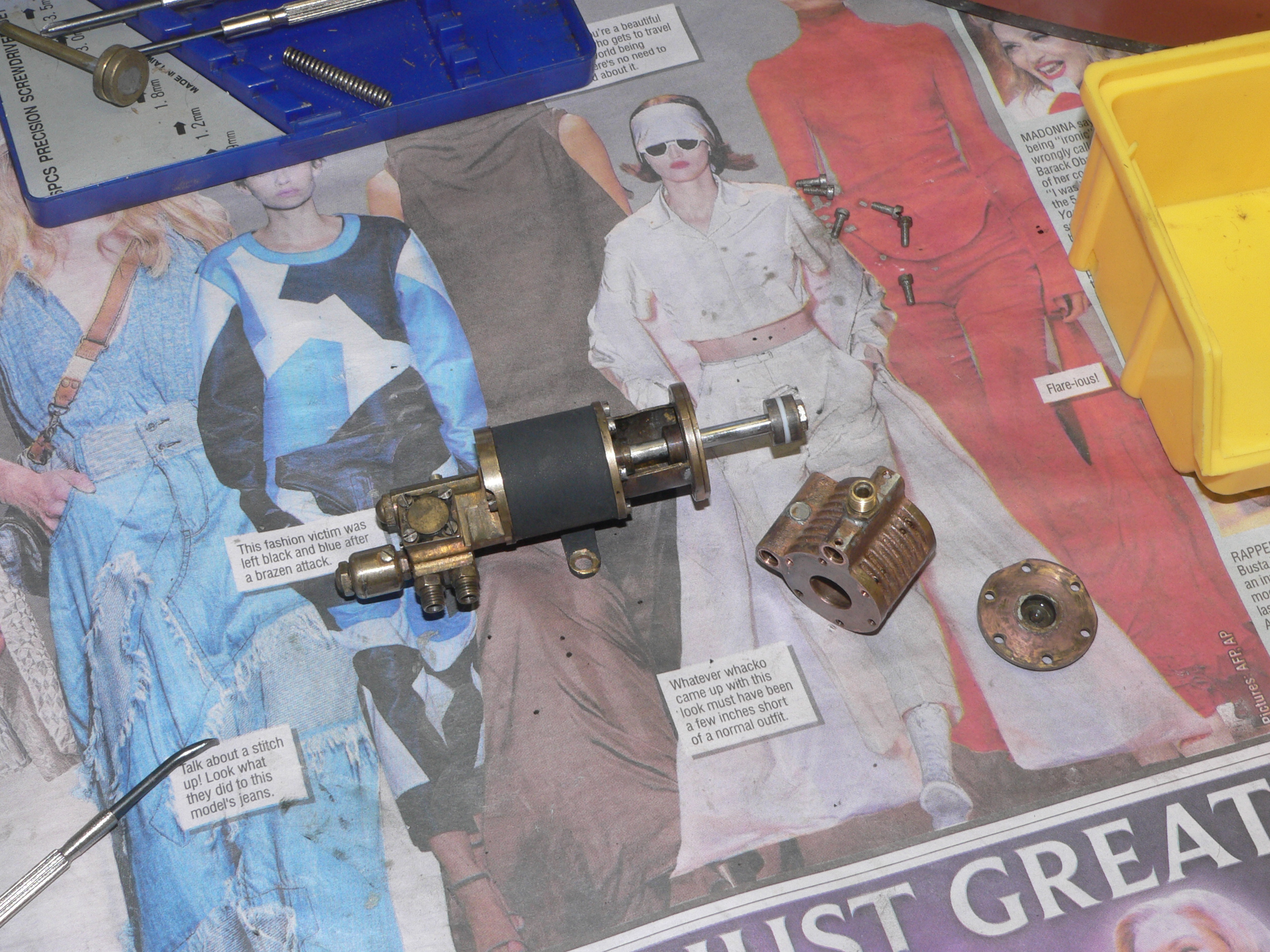
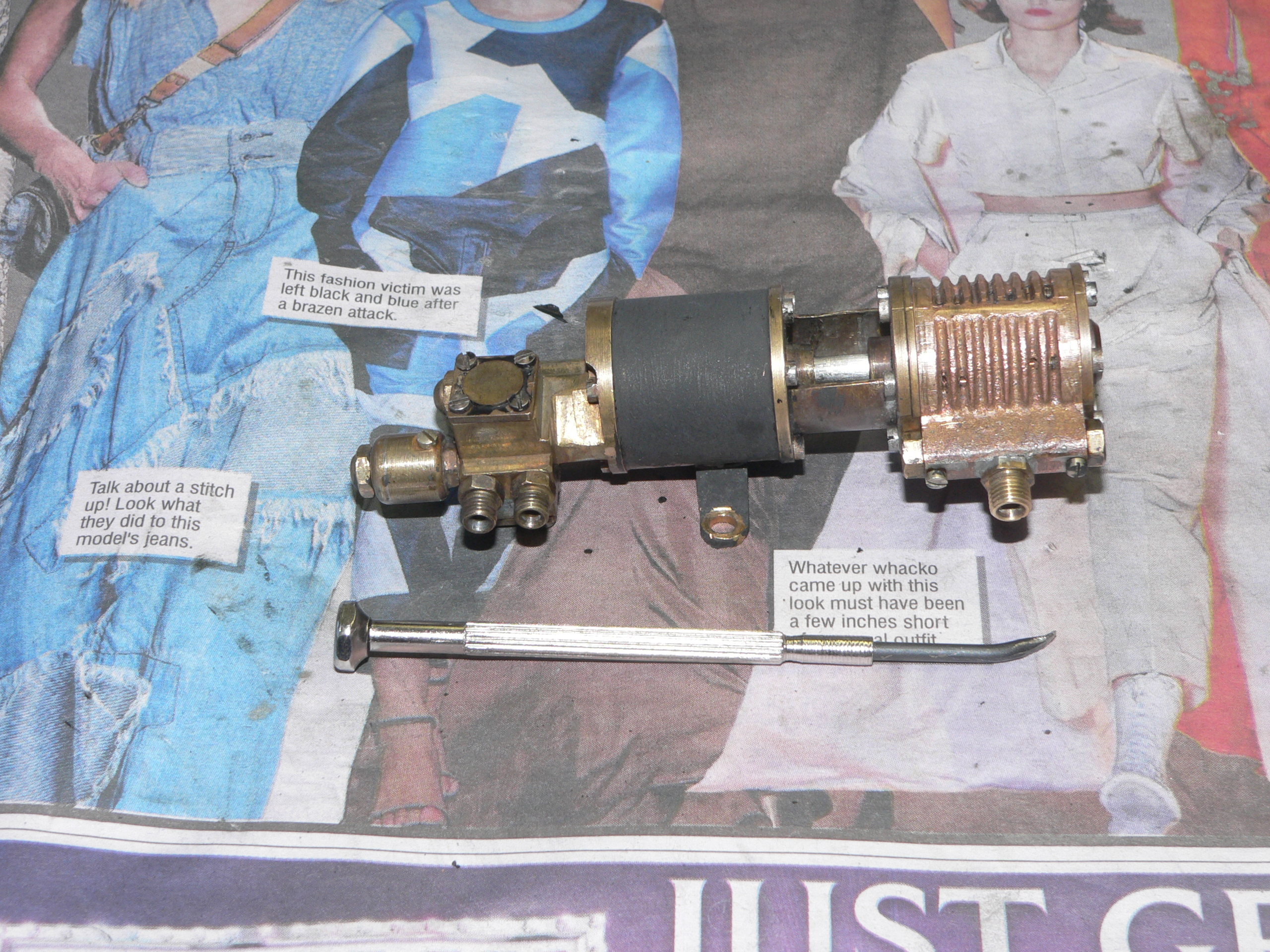
The donkey pump was prone to chattering which is generally a sign that it isn't primed. This happened after it had pumped for a while. I couldn't find any blockage or leak in the water supply so I dismantled the pump base and cleaned the valve seats. The design means that two of the four check valves need a backflow to seal and therefore the pump won't work slowly. Tiny springs under the two balls would help but would be very difficult to fit. Another idea is to fit lightweight plastic balls in these two valves.
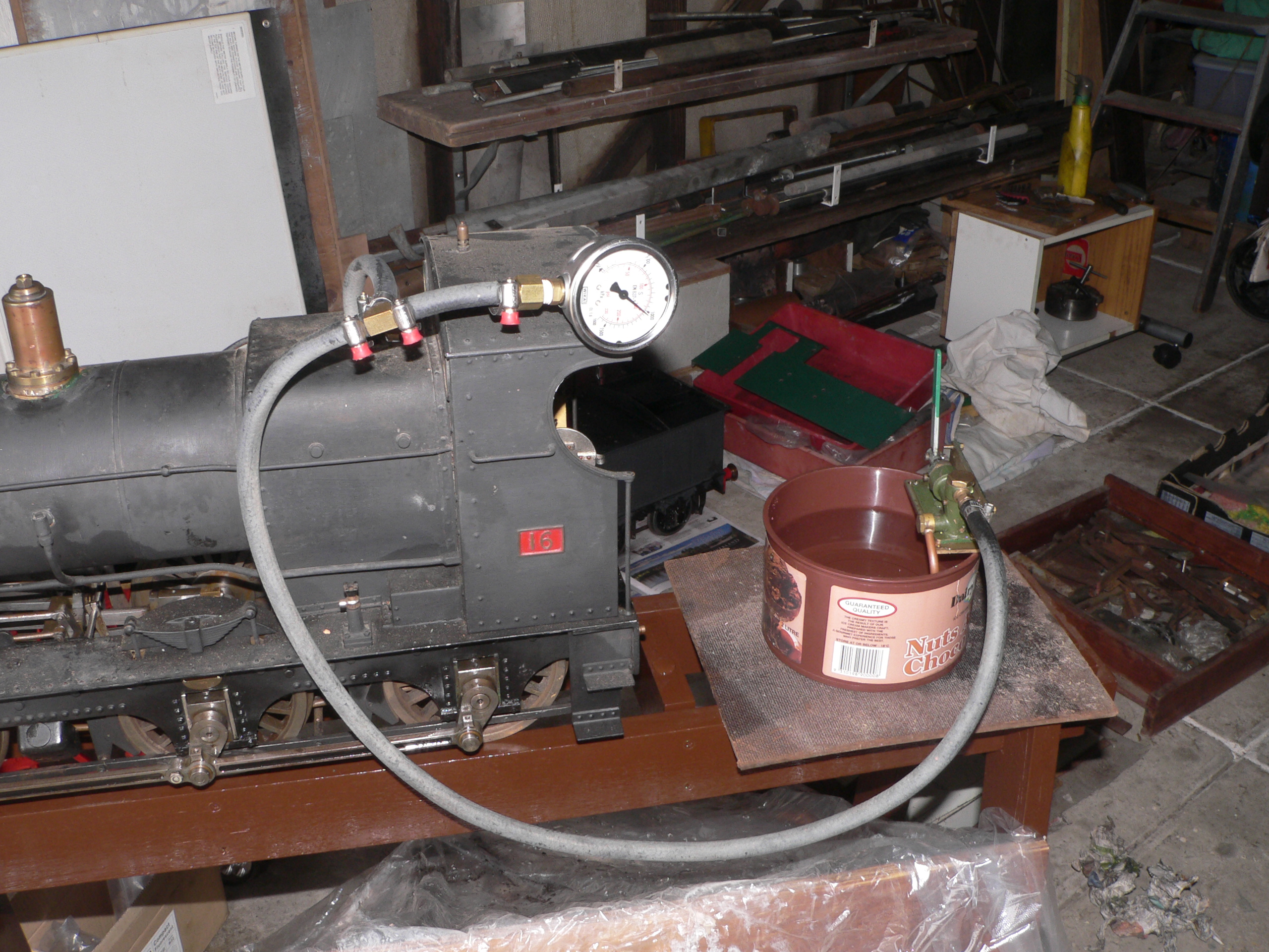
While the pump was apart I further distorted the non-seal seat in each valve. The valves have a seat at each end of the cylinder the ball lives in. One end has a good seat and the other has a distorted seat so the ball can't seal there. At the next steam test (Oct 4) I used the pump to maintain the water level. It worked much better than before but still needs manual priming sometimes (loosen the delivery pipe union). Maybe the water in the delivery pipe boils and blows the feedwater back out of the pump or maybe it's a combination of slight leaks in the pump seals and the negative delivery pressure because the feedwater level was lower than the pump. In the pictures below the feedwater is in the yellow container. My hand pump and gauge is connected to a clack valve so I can use my gauge to test the boiler pressure without subjecting it to the steam heat. The brown water is due to boiler treatment not rust.


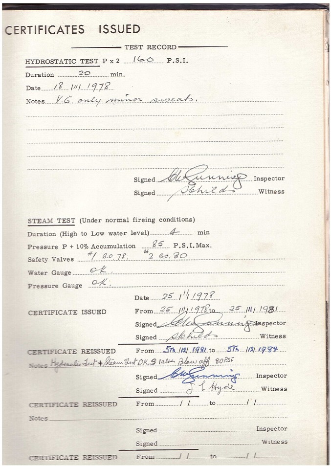
The boiler registration code is "NA.78.91". "NA" is the code for Sydney Live Steam Locomotive Society so I contacted Warwick Allison who is the President there. He was most helpful and sent me a scan of the boiler records that night. What great service ! He also told me that most old boilers had the registration code stamped on the dome base rather than the backhead as is common practice now. The boiler was registered in 1978 and renewed in 1981. The hydrostatic test was done at 160psi and the boiler is approved for 80psi. Luckily the 160psi matches my recent hydrostatic test.
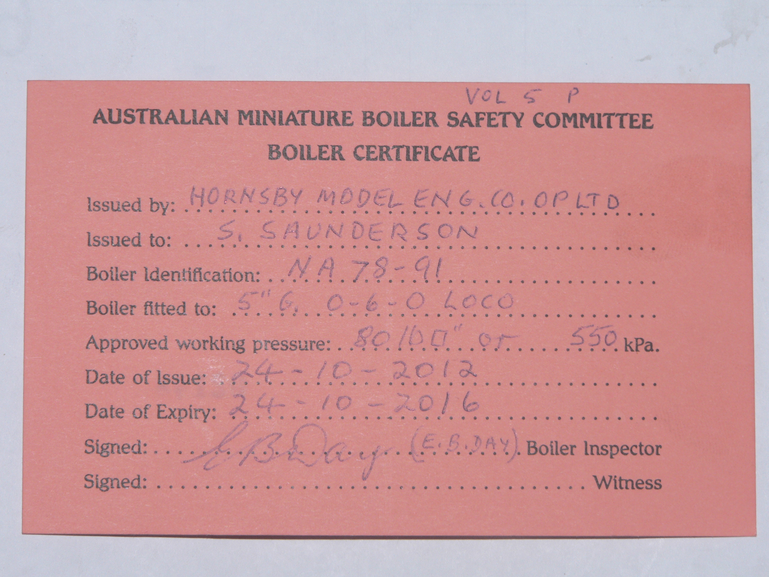
I had a boiler inspection booked for October 27. On the Wednesday before I went to Galston Valley Railway (GVR) for a work day. Early in the day I heard that inspections are sometimes done on a Wednesday. So I raced home, rang the inspector and got the OK. I loaded the loco and assorted paraphernalia in the car and went back to GVR. Brian (the inspector) was there and we did a hydro test and then a steam test and Brian issued me a boiler certificate.
Most passenger carriages at Galston Valley Railway have fail-safe vacuum brakes. These are on by default and released by vacuum in the train pipe. I don't expect this little loco to pull a full carriage around the hilly track but it should be able to act as a pilot loco assisting a larger train loco. The standard practice when double heading is that the second loco controls the vacuum brakes. This is done because most locos have an ejector connected directly to the train pipe and this pipe goes to the back of the tender only and then to the passenger carriages. I'd much rather have the lead loco (the pilot loco) control the brakes and the second loco (the train loco) should have the ability the apply the brakes if required. This requires a more complicated approach where the ejector is connected via a check valve and each loco has a leak valve to reduce the vacuum. A big advantage to having a leak valve is that the driver can leave the ejector on and use the leak valve to adjust the vacuum and therefore the level of braking.
For this loco I've got a leak valve in my bum truck. So the loco needs a train pipe from the front buffer beam to the back of the tender, an ejector connected via a check valve, and a vacuum gauge. I bought an ejector and check valve from DNC and made an assembly that fits under the footplate. There isn't much room here and I wouldn't like to work on this when the loco is hot.

The riser on the left is for the vacuum gauge. The check valve is in the middle and arranged so the valve closes by gravity to reduce leaks and delays when another loco is creating the vacuum. The ejector is on the right and has a discharge tube to ensure the steam won't get into the ashpan. The risers are extended so the union nuts are above the footplate. There are two train pipe connections at the bottom (one forward and one back) and the port on the left is for the leak valve in case I decide to fit a brake control valve in the cab. If I make another of these assemblies I'll fit a check valve from the ejector suction port to atmosphere. Then if the ejector gets dirt in the annulus I can block the discharge tube and turn on the steam which will blow through to the suction port and atmosphere and hopefully clear the blockage.
Here are before and after views of the cab. The assembly is below the footplate and secured to the brass angle under the firehole. The turret has been extended to the right and the new steam valve is for the ejector. The vacuum gauge on the left is secured by a bracket affixed to the side of the cab. The train pipe is slightly to the right of the drag box.
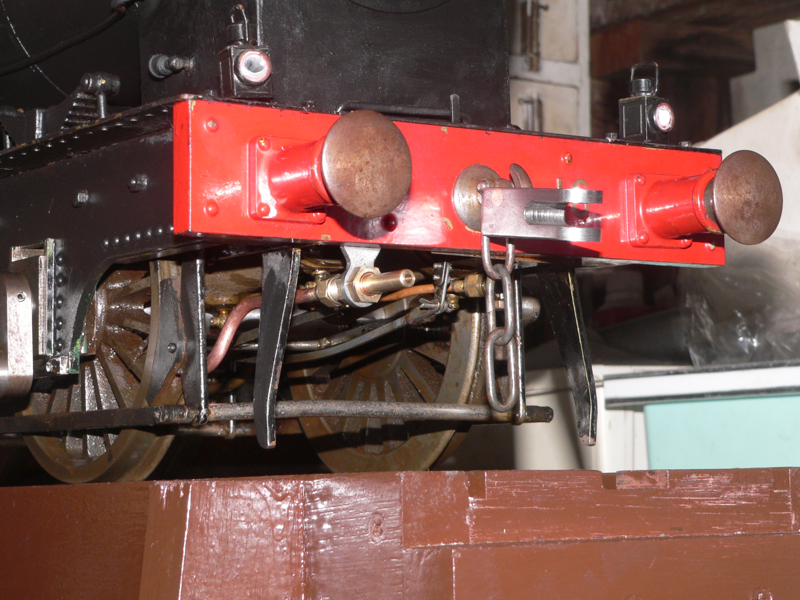
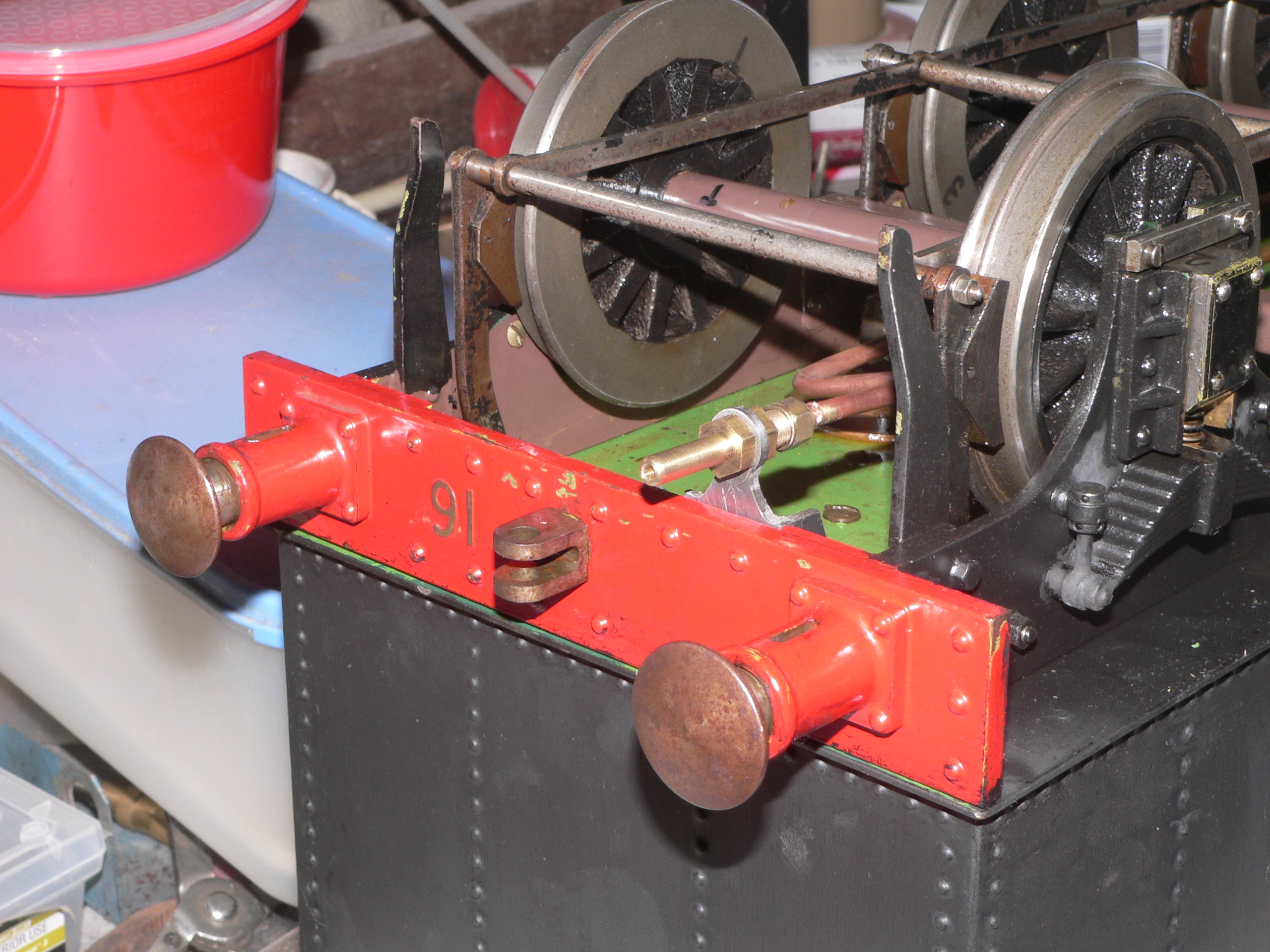
The AALS standards recommend the brake pipe spigot be at coupling height (82mm) and 90mm to the left of centre when facing the buffer beam. I can't go 90mm from centre and I don't want to drill holes in the buffer beams. The spigots are about 40mm to the left and mounted under the buffer beam. Also, I've made an adaptor for the front hook so I can couple using a standard bar. This is easy to fit/remove by lifting the front so the adaptor is vertical and yet it can't come off when horizontal. The adaptor also compensates for the fact the hook is higher than the 82mm standard.
Testing on October 24 shows the ejector doesn't use too much steam and will pull more than 26" of vacuum. I suspect the gauge might be a bit optimistic. Still, this is plenty of vacuum to release the brakes.
After the boiler test on October 24 I did a few short runs in the loco service area and all looks great for a big test on the weekend. The footpegs on the bum truck are too far back so I removed the bar and fitted it to a stretcher under the tender. This made the driving position much better. The tender might need heavier springs to cater for the extra load. The firebox door has no catch and was too free so I fitted a bent washer to the pivot to act as a brake.
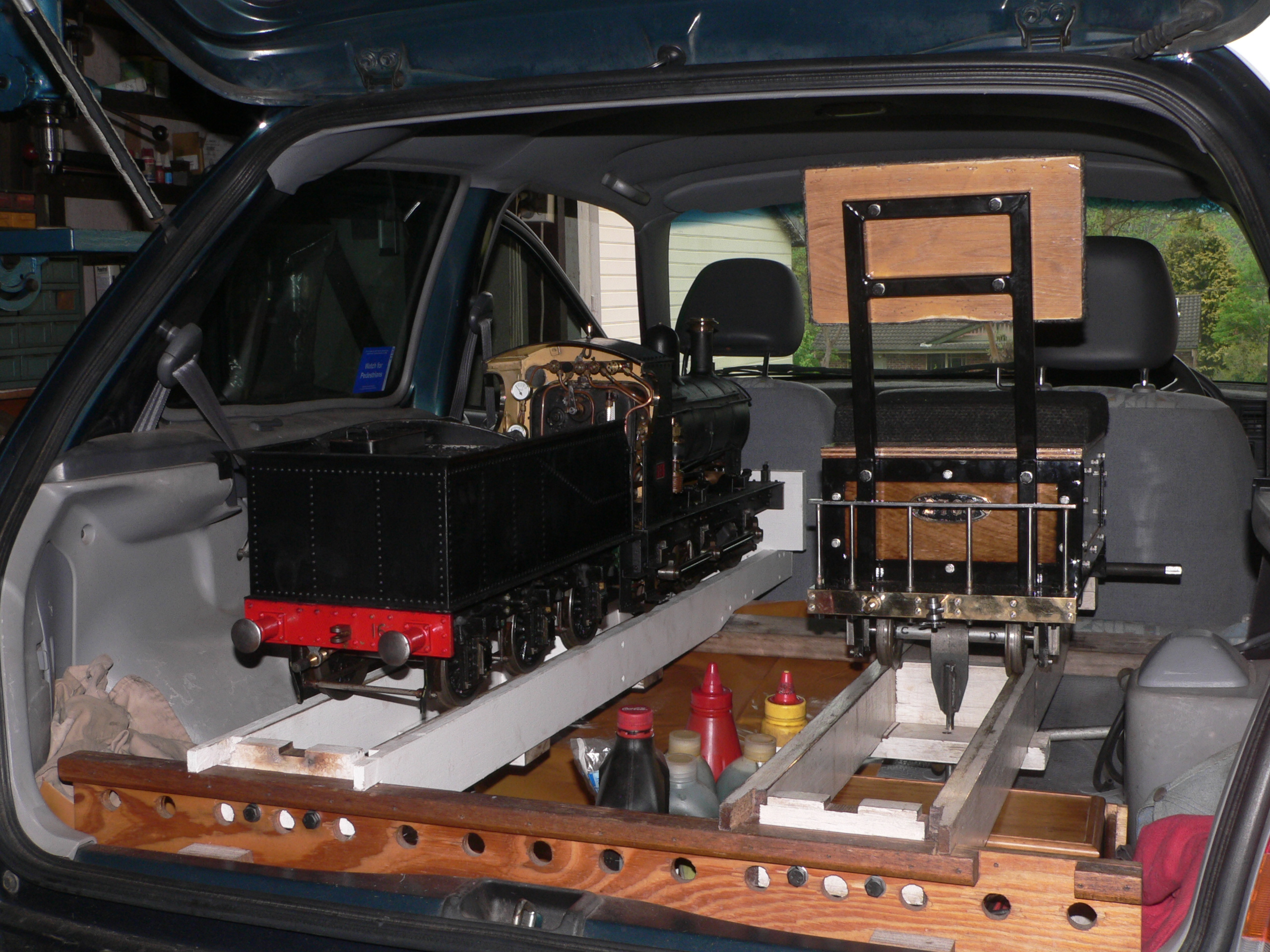
I don't think my little car was designed to transport a loco and bum truck. Loading takes a bit of time and effort and leaves no room for a passenger. After an early start clearing the track (sticks, rocks, etc.) I steamed the loco while waiting for someone else to arrive at the site.
The boss arrived at about 8am so I started the test run. After a few laps and tests on some hilly branches I coupled up two carriages as a test load. This went well so I tried with two passengers and then four and then five. The little loco has far more power and tractive effort than I'd expected. Unfortunately I don't have any pictures because I was driving. The ejector for the vacuum brakes worked well but the steam consumption does mean I have to run the blower when coasting to maintain boiler pressure. The ejector works best when the steam line is about 40psi so when the boiler pressure is higher (hopefully all the time) it's worthwhile throttling the steam supply. Another control that wants constant attention.
The next day we did another test. A friend brought his P class so we could try double-heading on a train. I had to collect the carriages first and the little loco (SMJ 16) did a sterling job and dragged the four carriages up to the yard at the top of the hill. There we coupled up Greg's P class and his full-size driving carriage and practised synchronised driving for the rest of the day. This went well except for when I was burning char dust and showering Greg with embers.
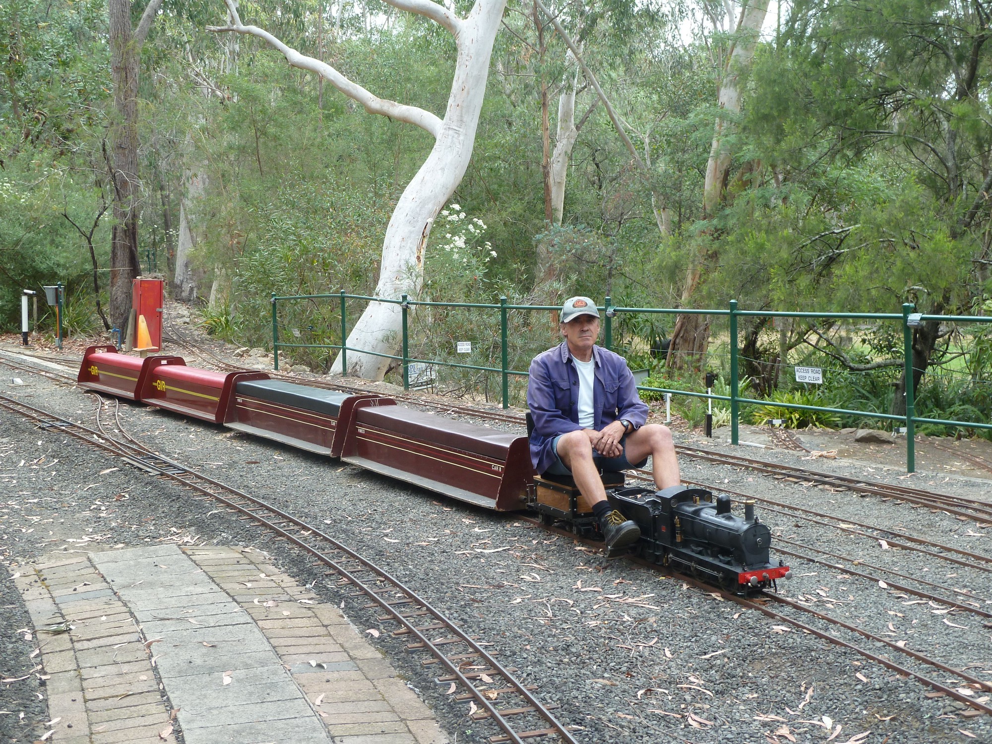

Here is me looking a little pensive on the loco and train. This is after I'd dragged the four carriages to the top yard. The second photo shows Greg looking bemused and wondering how the little loco hauled all the carriages up the hill. The ruling grade is 1 in 70 with some humps and curves that make things a little bit harder.
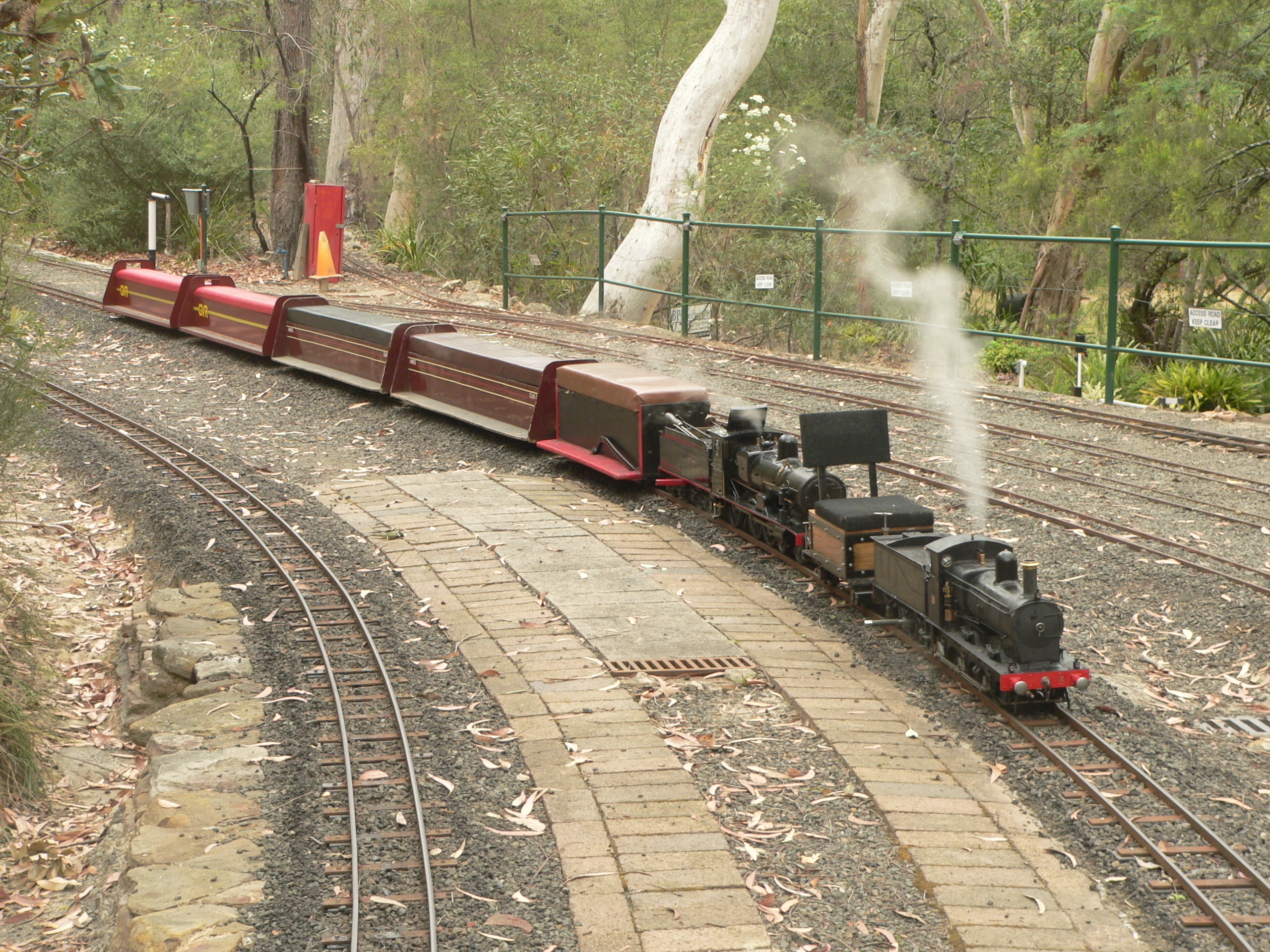
Here is our test train. Greg's driving carriage is built like a tank and weighs a ton. The passenger carriages are substantial but lighter.
That's enough heavy-duty testing for the moment. Now I'll practise light duties and driving and firing this loco. It likes trundling along with a small train and will last much longer if treated carefully.
The loco was built by Jack Esdaile and finished in 1978. Graeme Belbin bought the loco in 1985 and has preserved it well but never run it. It has been kept indoors as a static exhibit and this is why it is still in such good condition.
Graeme was so pleased to see the loco running last weekend that he agreed to sell it to me. This was a very generous and appreciated offer because the loco has been in the family for so long. Now I've bought the loco and am the proud owner and responsible party for this little loco. Let's hope it goes for many years.
The next chapter of this report shows changes and repairs to this locomotive.
Last modified 2013-01-20