
Sandberg Water Pump
|
Sandberg Water Pump |
|
Warrick Sandberg supplies locos and parts for live steam railways. One of his products is a 1" scale Westinghouse air-compressor that is a steam-powered water pump. I was impressed with these pumps before but now I've pulled one apart I'm more impressed due to all the hidden attention to detail. This is an amazing piece of engineering.
These pumps are now available from E and J Winter - Bolton Scale Models which sounds great to me because when I wanted to buy one years ago there was a long waiting list and no estimate of delivery. I think the original design came from Ernie Winter.
The pump here apparently seized one day after lots of use and probably no oil for most of the day. The loco does have a displacement lubricator for the pump and I suspect the pump runs dry for some of each day as this lubricator is always empty at the end of the day. We tried to free the pump in situ but this didn't help so I removed it and disassembled it as far as possible. The information below is offered to assist anyone who may be considering such a task. The pump is now working but does need further attention. This report is a work in progress and the latest comments are at the end of this report.
The pump is held together with 1/8" AF bolts and two 1/8" AF nuts. I made a 1/8" AF socket from a 1/4" BSW grub screw (thanks to Stephen Carter for this excellent idea) and bought two not-very-good tiny AF spanners from an online shop in Queenland. I had to grind the spanner jaws to make them fit the bolts and also grind away most of the body to enable access in tight corners. One spanner is 3.2mm AF and it's tighter than the 1/8" AF spanner. I'm not too sure about the ELORA brand.

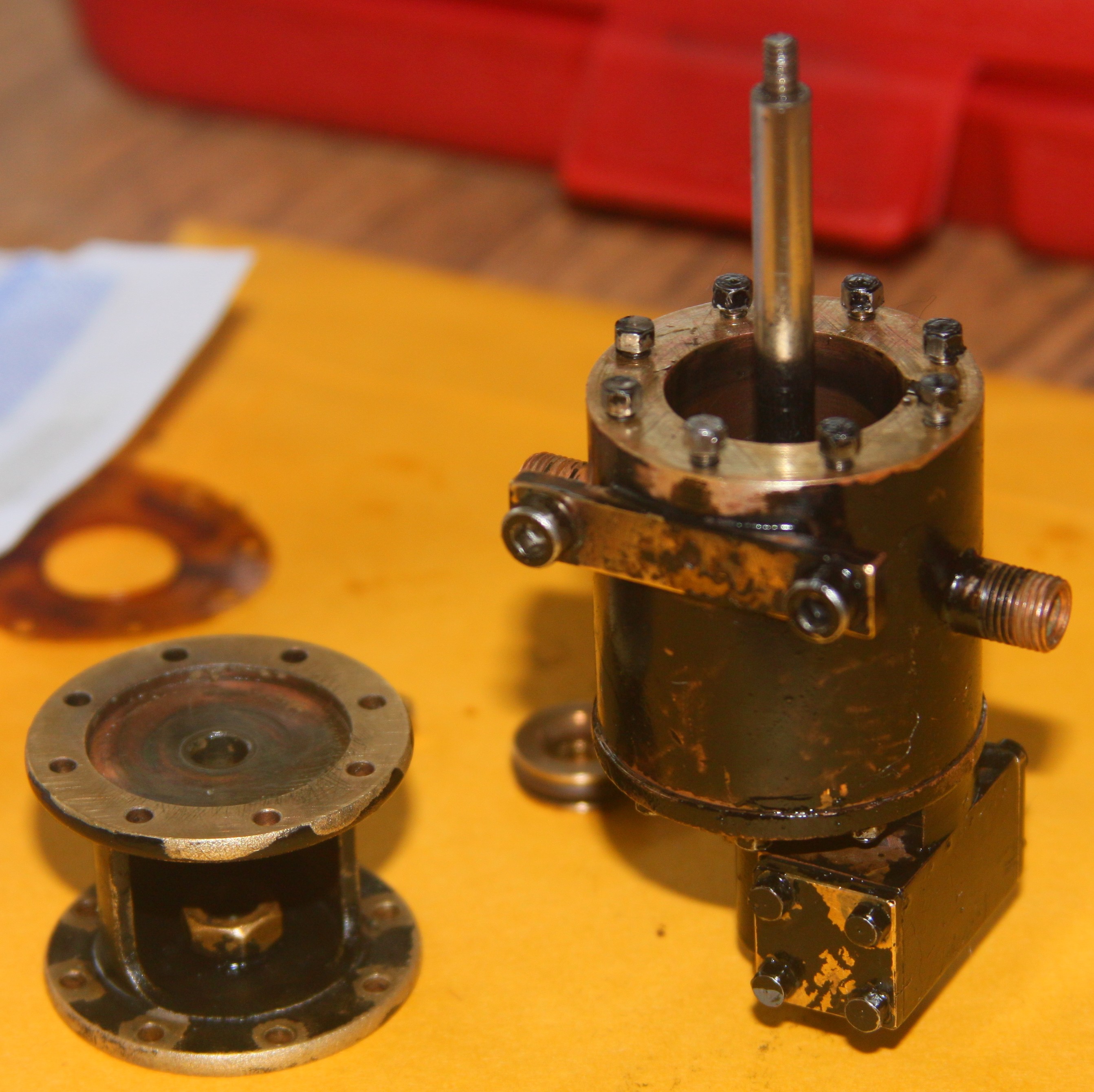
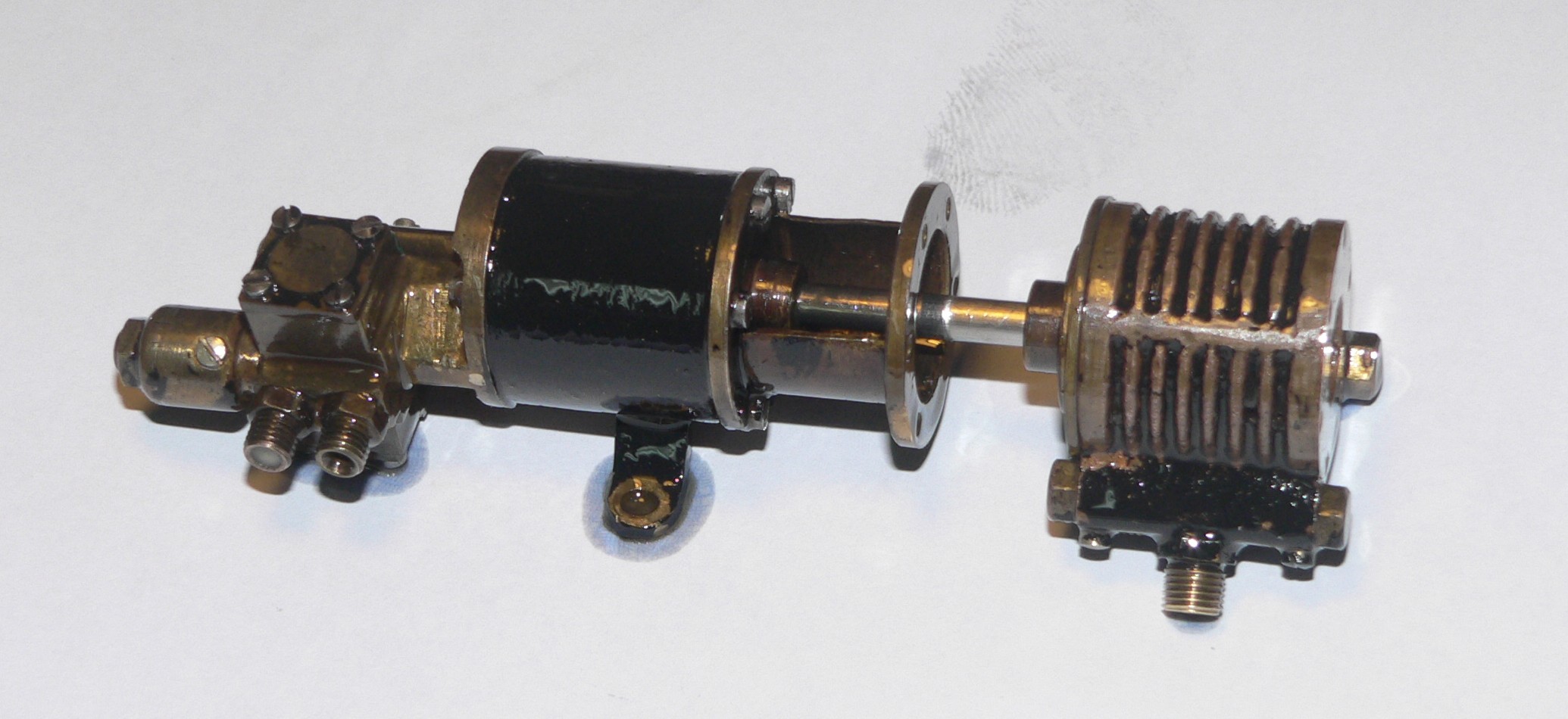
Here is the pump when first disassembled. The water cylinder (1/2" bore) is on the top left, then the pistons and rod, then the steam cylinder (3/4" bore). My set of spanners is on the left. The connecting piece and discs are in the middle. The discs house the seals for the piston rod and live in the recesses in the connecting piece. On the right is the top cover for the steam cylinder. This contains the pilot valve and the shuttle valve. The rod extending from this cover is moved by the piston at each end of the stroke and this moves the pilot valve. This changes the steam pressure at each end of the shuttle causing the shuttle valve to move and change the steam and exhaust flow to each end of the cylinder.
I couldn't remove the pilot valve rod. It has collars at both ends and the sealing bush in the top cover appears to be pressed in. Perhaps it was pushed in from the top and then the big collar at the visible end was soldered on. The rod can be pushed far enough in at the bottom so the top protrudes and the slide valve can be removed.
The shuttle valve has a piston at each end and a slide valve in between. The pistons each have a groove filled with packing which looks like waxy string. If you remove the shuttle valve be careful not to dislodge the packing as it might then cause the valve to bind.
Both main pistons (steam and water) have O-rings (VITON ?) to seal in the bores. These seemed to drag quite heavily especially at the lower end of the stroke. I polished the bores using Brasso and this helped a bit. Coating the bores and rings with graphite powder made a big difference. There was no build up of scale or dirt in the grooves. Another possible cause of the seizure was that the shuttle valve was very tight at each end of its travel. Removing the shuttle valve and cleaning its bore helped here.
The water piston can be removed from the rod after undoing its retaining nut. The steam piston appears to be pressed on the rod. This might be an issue if you need to replace the piston rod. Both pistons should last forever as they don't touch the cylinder walls.
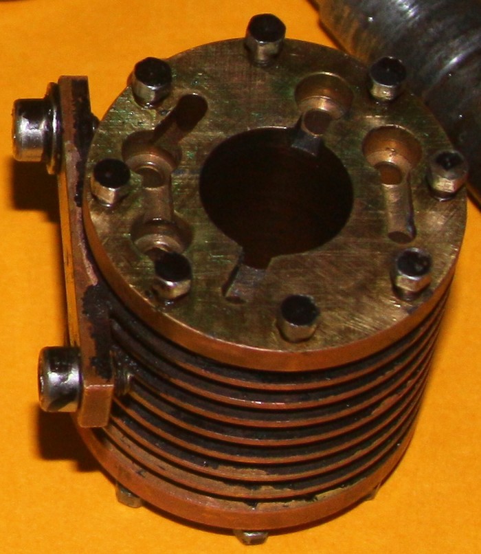
The top of the water cylinder contains the seats for the four check valves and connecting ports. This is a double-acting pump just like the real one.
Reassembly has started now. The pilot valve rod is inside the piston rod and held in by a cap screwed to the top of the steam piston. I made new gaskets for the cylinder covers and the shuttle valve covers from grease-proof paper painted with a graphite/oil mix. I kept all the bolts and nuts in their original locations in case things weren't quite as interchangeable as an optimist might assume.
Here I'm making the gasket for the bottom of the steam cylinder. The disc containing the sealing O-ring is in place. This will help locate the gasket when I make the holes for the bolts.
Here is the top gasket for the water cylinder. Before fitting the cylinder the water piston must be fitted. I wrapped the piston rod in thick cardboard and held it with pliers to stop it turning while I fitted the piston. The assembly here must be inverted and lowered onto the water cylinder as the top of the cylinder contains the stainless steel balls for the check valves.
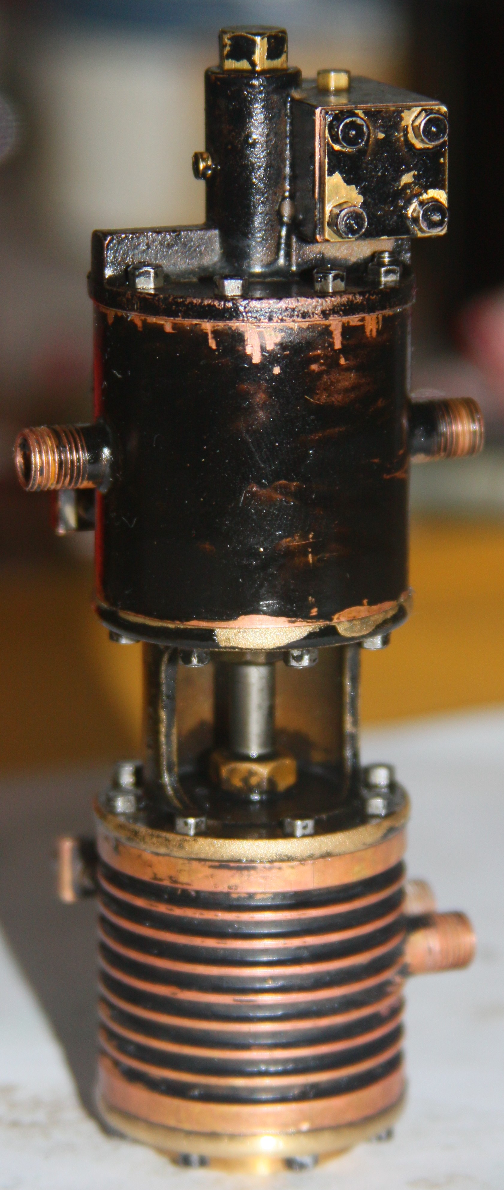
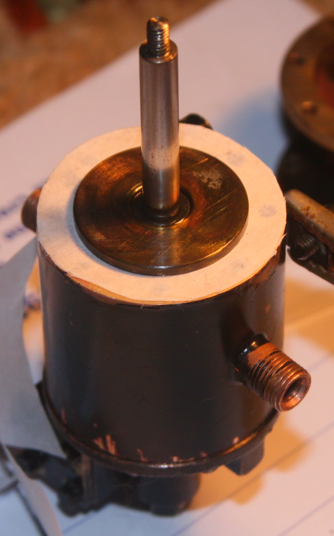
The pump is now back together and has been tested on compressed air. It doesn't look too pretty here so the next step is to give it a good clean and paint it. The original paint here is just enamel with no undercoat and I'll do the same and give it a final touch up once installed on the loco.
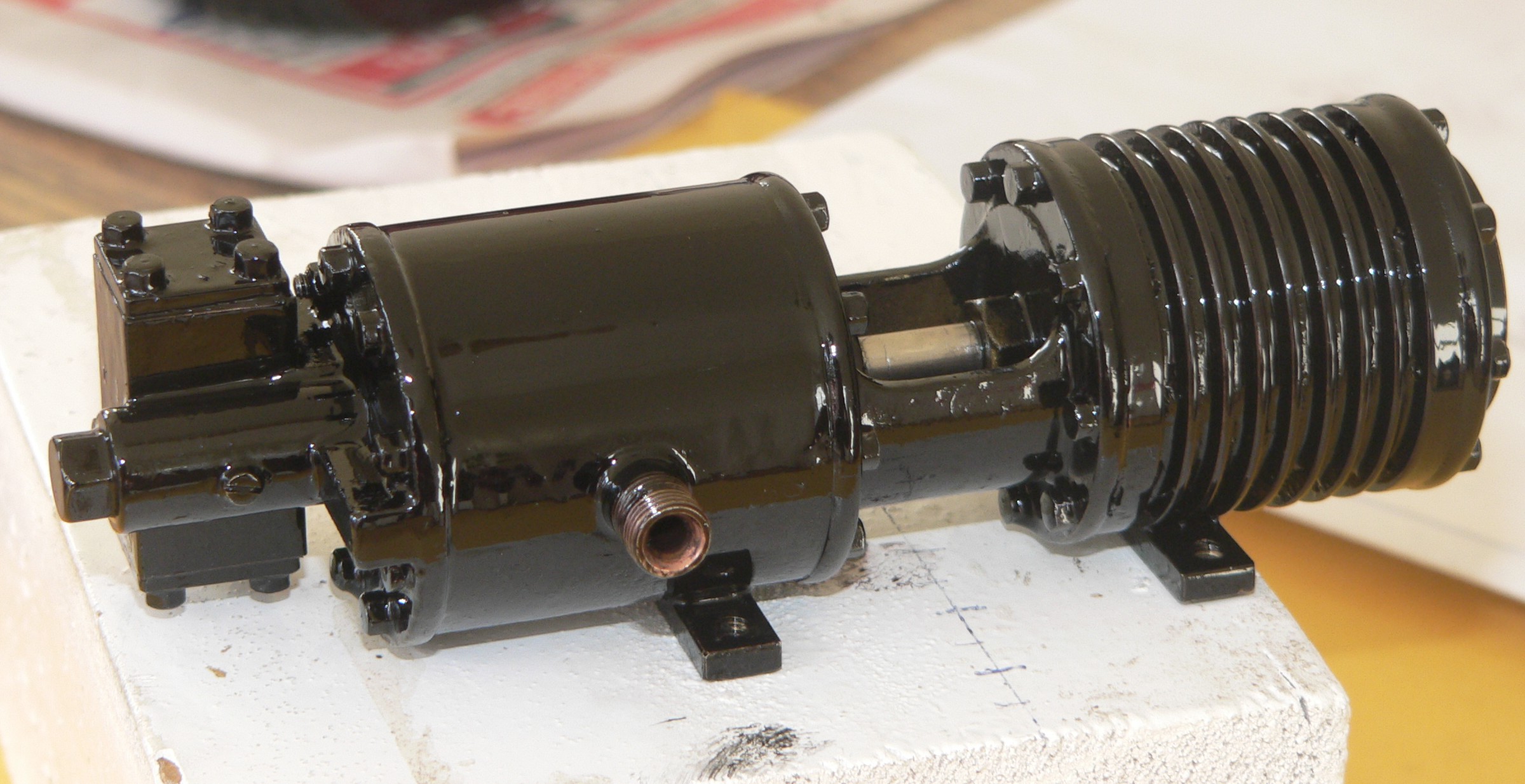
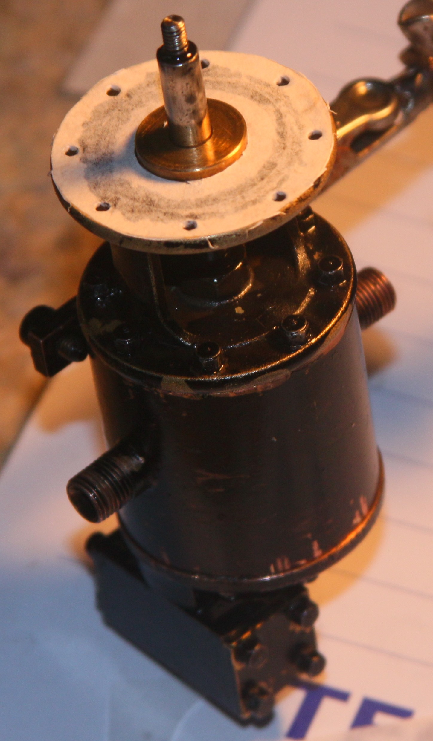
For the final picture here the pump is now painted and ready to return to its hard life out in the real world. The water cylinder will get a final lube with graphite powder before re-installation on the loco.
After the reassembly described here the pump was still jamming occasionally. When steam piston hits the bottom of the stroke and pulls the pilot valve down, the back of the shuttle valve is connected to the exhaust. The shuttle should then move back due to the pressure difference on the back piston. But it doesn't and it looks like there is leakage past this piston and therefore the pressure difference is reduced. The exhaust port is tiny and goes via the pilot valve so any leak past the shuttle valve piston will have a big effect. Loosening the back cover for the shuttle valve lets the pressure escape and the valve then moves. The shuttle needs to move freely and also the packing for both its pistons must seal well.
The leakage theory above seems flawed because reversing the shuttle (so the supposedly leaky packing is at the other end) makes no difference. The port to the pilot valve isn't blocked and the exhaust port from the pilot valve is okay so it looks like pilot valve isn't stopping in the right place to connect the back port from the shuttle valve to the exhaust.
The downward motion of the steam piston is arrested by the change of steam pressure caused by the movement of the valves. However, if the piston doesn't stop quickly enough it pulls the pilot valve rod down onto its stop. Over time this impacting has deformed the bottom collar slightly and the pilot valve travels down too far and the exhaust cutaway in the valve no longer connects the port from the shuttle valve to the exhaust port. This stops the shuttle from moving and reversing the steam flow to the steam cylinder.
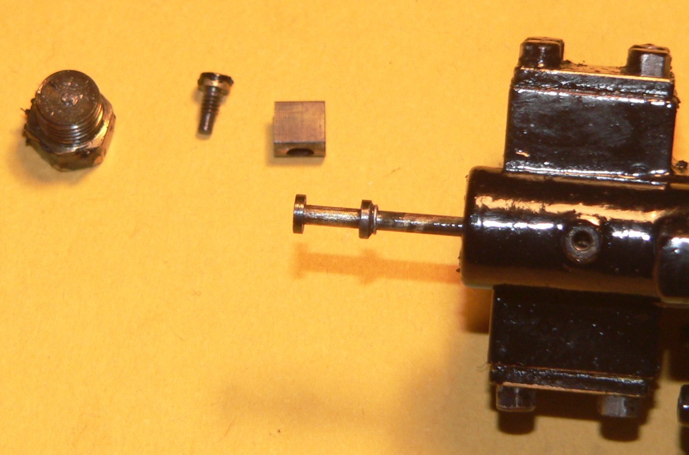
This picture shows the pilot valve rod. Under the lower collar is a 0.3mm collar (a piece of fuse wire) I fitted for testing. This collar restricts the downward movement of the rod and valve and fixes the jamming of the pump. After this test I fitted a 0.7mm collar and this is being tested.
The deformation (or hammering of a stop) is probably caused by the rapid movement of the pump when the water pump isn't primed. So much for the idea that it was a lubrication problem.
After a few runs (and good tests) the pump is working properly except that it leaks from the piston rod glands because the piston rod (3/16" dia SS) has been marked. The paper gaskets are okay so far. I'll use proper jointing when the pump is next dismantled to replace the piston rod.
2012-07-08 : The little pump is working and the improvements (proper repairs) are still pending. Sounds good to me.
2012-08-06 : I'm working on a loco that has an early version of the pump that I believe was built by Jack Esdaile. I haven't found anybody who knows where the design or plans came from. It's smaller than the later ones and better scaled for 1" scale locos. The pumping rate is less due to the smaller bores and perhaps not enough for a 1" scale loco. A miniature version of a miniature marvel. The water piston was seized but freed after removing the covers and oiling and pushing it. If only all repairs were that simple. Subsequent testing highlighted problems with the check valves. I cleaned these and further deformed the non-seal end of each valve chamber. This improved things and the pump works well. The shuttle valve does bang against its covers so I might have to add gaskets to cushion the blows.
Check my homepage for contact details if you have any questions or feedback. Comments about the content or design of my pages might help me improve this report and will be appreciated. The text size in these pages is variable and specified by your browser settings so you can change it for your viewing convenience.
Last modified 2012-12-30